Engineering Class Project
⚙️ Axial Flux Motor
Spinning chakras 𖣐
The Design
What is Axial Flux?
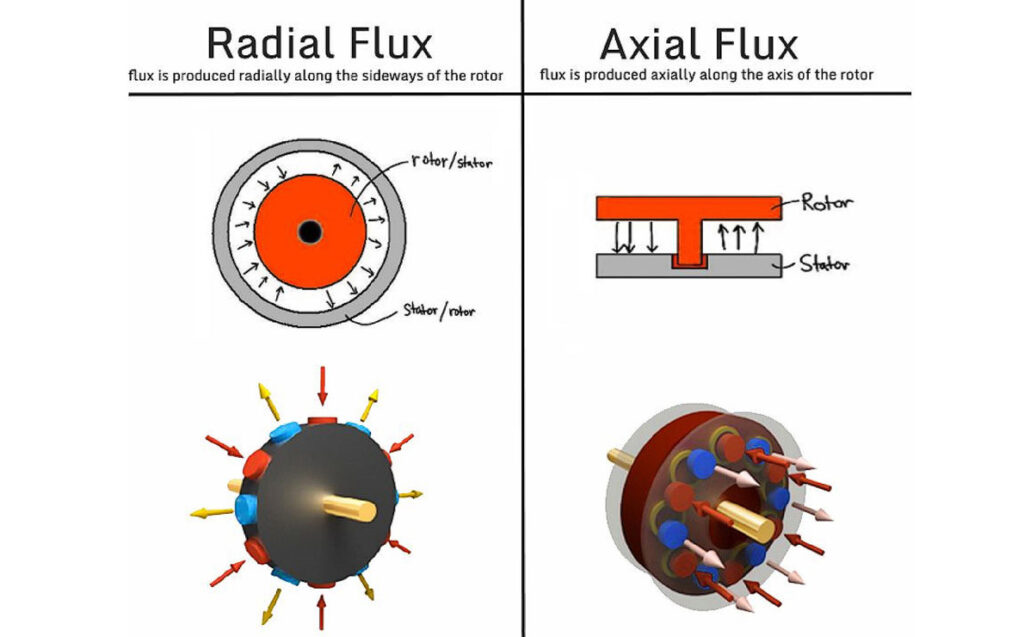
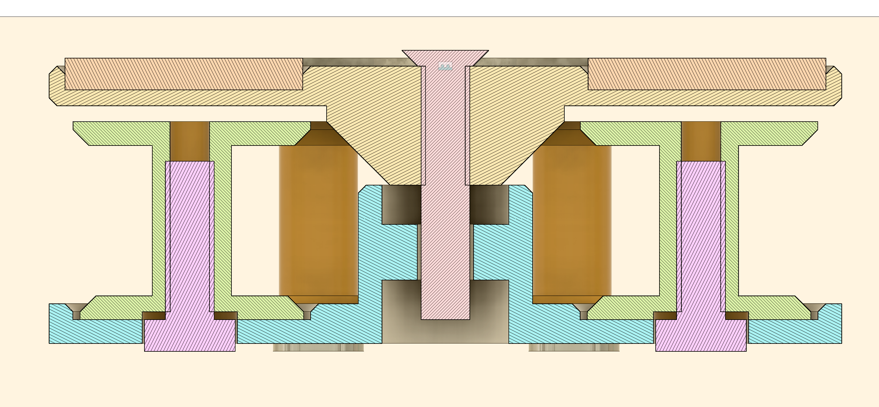
In a conventional radial motor the magnetic field travels outward from the centre of the rotor. Axial flux flips this: the field runs along the axis of rotation, so the stator and rotor face each other like two plates. The magnetic path is shorter and more direct, which gives higher torque and power density. The flat open winding layout also lets air move around the coils naturally.
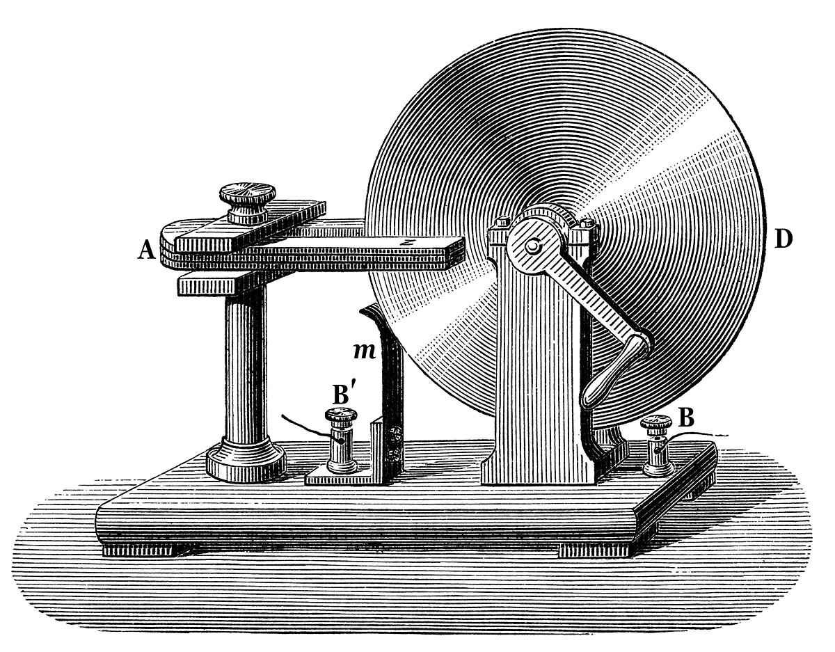
This geometry is used in EVs, drones, and supercars. Faraday demonstrated the same basic principle in 1831.
When the class project came up to build a motor, I just found this design really cool. It looks like a chakra or a spinning disc. I enjoyed reading about the history of it and wanted to build one.
The Build
What We Made
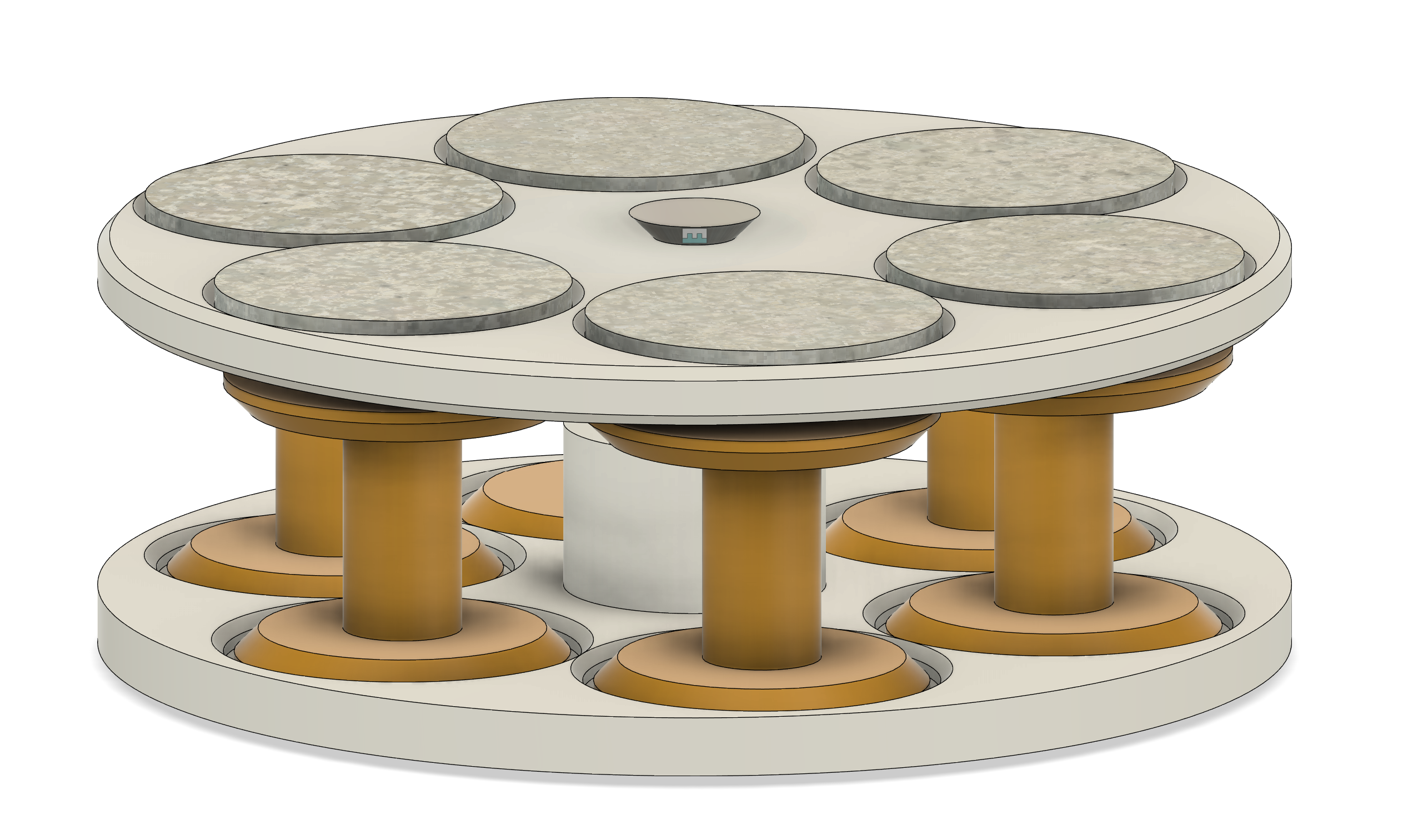
Mechanical
- 1 bearing, 3D-printed shaft
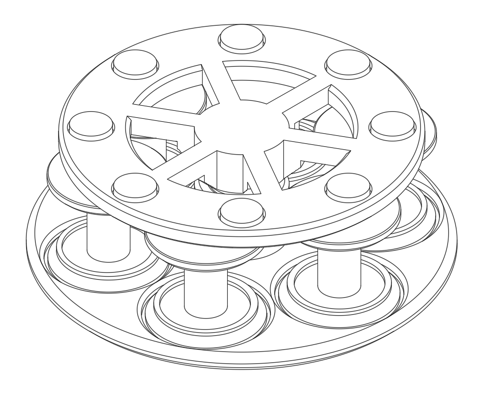
- 3D-printed rotor discs and independent spool bodies for each winding
- Total weight: ~250g
- Lightweight and easy to disassemble and rewind
Magnetics
- 16 neodymium magnets, alternating orientation around the rotor
- Doubled up magnets to increase field strength
- Axial field path through facing stator coils
Electrical
- Six 150-turn coils, 28-gauge copper wire, 2A max per coil
- Operating voltage: 15V nominal
- Current draw: ~300mA under typical load
- ESC for speed regulation and constant voltage supply
The Process
How It Came Together
Everything was modelled in Fusion 360. The geometry came from research papers since proper hobbyist documentation for axial flux motors barely exists. Winding tutorials in particular are nonexistent at this level, so we figured it out ourselves through trial and error.
The shaft went through a few redesigns to find a version stable enough to support the rotor without wobble. We doubled up the magnets on the rotor after testing showed the single layer was not producing enough field strength.
Honestly it came together more smoothly than expected. The most involved part was getting the windings to align correctly with the ESC, but even that sorted itself out. It also felt more engaging to learn when we were doing the unconventional thing.
Iteration
Problems Along the Way
- Heavy rotor produced low torque. Redesigned it to be as light as possible.
- Large air gap between shaft and rotor was limiting speed. Reduced by 1mm to tighten the magnetic coupling.
- Uneven shaft tolerances meant it would not spin continuously. Standardised all coils to 150 turns for uniform winding geometry.
- Hall effect sensor polling was too slow to keep up with motor speed. Documented as a known limitation for future work.
The Result
Our Axial Flux Motor in Action
It spins well. Actually, it spins hard enough that it hurt to hold. We pushed the voltage past nominal and it handled it fine. Lightweight, agile, and it works.